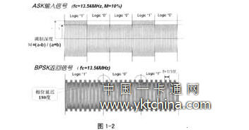
1. Types of non-contact IC cards and international standards ISO14443 also contains three types of A, B, and C (of which type C is undetermined). Table 1-1 compares Type A and Type B from the card reader to the IC card and IC card to the card reader. The second-generation ID card uses a B-type non-contact IC card chip. The card reader sends a radio frequency signal with a carrier frequency of 13.56MHz +/- 7KHz to the card, using 10% ASK modulation, and NRZ (not In the keying mode of zero return, the data transmission rate is 106/212 Kbps; the return signal of the chip in the card adopts the subcarrier modulation mode of BPSK, and the frequency of the subcarrier is 847 KHz. Figure 1-2 shows a comparison of ASK and BPSK signal waveforms. For the ASK signal, it defines the logical "0" or "1" of each data period based on the magnitude of the sine wave amplitude (a or b). At the same time, we define the modulation depth M = (ab) / (a ​​+ b) For the BPSK return signal, we judge the logic "0" or "1" with the starting level of each data cycle, so for the period of "0", "1" conversion, we can see that the sine wave has 180 The phase shift of degrees. 2 non-contact IC card chip and its test requirements Table 2-1 lists the test items that are usually performed in the design evaluation and mass production of the contactless IC card chip. Some of the test items are common SoC test items, and the test method used is For the design evaluation test, the tester is required to transmit/recognize various signals (ASK/BPSK) specified by IS014443 type-B to realize its RF communication function. The digital signal driver of the digital signal test portion of the integrated circuit test system generates a digital signal, and the digital signal is converted into a sine wave signal of the same frequency and amplitude by the filter circuit of the ASK signal generator; A sine wave signal of amplitude (in accordance with IS014443-B type) is required to be connected to the chip to be tested, and at the same time the back end of the amplifying circuit (amplified signal) is connected to the monitor, which functions to be sent to the chip antenna. The voltage peak-to-peak and modulation accuracy of the RF signal are corrected; under normal circumstances, the BPSK return signal of the chip is detected by the RFID module, amplified and further sent to the demodulation circuit for decoding, and finally the demodulated circuit will demodulate the digital code. Return to the digital signal comparator of the digital signal test section, compare it with the previously saved standard code to see if it is the same, to determine whether the chip's return signal is correct. In large-scale mass production testing, two methods can be used to achieve multi-chip simultaneous testing for different situations: 4. Summary Adhesive Caddy,Adhesive Shower Caddy,Self Adhesive Shower Caddy,Adhesive Shower Shelves Jiangmen Sunbond Houseware Manufacturing CO.,LTD , https://www.jmsunbondhw.com
According to the working distance between the card reader and the IC card, the non-contact IC card can be divided into the following four categories (see Figure 1-1), wherein the second-generation ID card uses the short-range communication type, that is, the non-contact conforming to IS014443 IC card, its effective range is about 10-15cm, and the typical operating frequency is 13.56MHz. 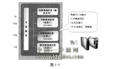

From the perspective of IC test requirements, the contactless IC card chip can be divided into two parts (see Figure 2-1): the RF part and the logic part. The logic part is composed of embedded CPU/MCU plus memory (generally non-volatile EEPROM, etc.), which is no different from ordinary SoC chip test; RF part is composed of RF antenna terminal, RF signal generation circuit, Demodulation circuit, RF interface circuit and so on. In addition to the common SoC chip test items, there are RF communication tests that receive/recognize RF signals from the outside through the antenna terminals and perform feedback. 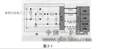
ED (DwCp and DC/AC test units used in ADVANTEST's T6000 test system); and RFID modules (RFID test) for the remaining test items, including Vcc rectified voltage, communication experiments, etc. Application module). Low-cost test requirements are achieved through the RFID module, combined with the digital test capabilities of the T6000 test system. The RFID Module is at the heart of the entire test solution. 
In addition, for large-scale mass production, multi-chip simultaneous measurement needs to be solved at a low cost, and interference between the chip and the chip should be avoided as much as possible.
3 Non-contact IC card chip overall test solution
Figure 3-1 is a schematic diagram of a non-contact IC card chip test solution. The top half of the figure is the tester, the RFID module and the chip to be tested from left to right. The lower part is a photo of the IC card test module and tester. The specific working principle is as follows: 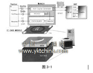
The advantages of this test method are mainly threefold. First, compared to the common test method that requires the IC tester to require a more expensive mixed-signal test component to transmit the identification RF signal, the solution only requires ATE to have the general digital circuit test function without having to take up too much of the tester. In addition, the entire process of testing and signal processing (including the processing of analog signals) are almost always performed at high speed through the RF module; therefore, the test time is greatly reduced compared to the use of mixed-signal test components. Finally, the RF module used is directly mounted on the test circuit board, completely separated from the tester body, and can be easily and flexibly disassembled. When multiple chips are tested together, only a plurality of RF modules can be used.
Figure 3-2 shows the ASK waveforms acquired by the communication test of the non-contact IC card chip using the above test method. Figure 3-3 shows the BPSK return signal of the non-contact IC card chip to the chip. 
(1) If the return signal period offset of all DIEs in the same measurement is within 1 ETU (one data unit, 1 ETU = 16 cycles), the test system can identify the received asynchronous signal and receive all the tested chips. The return signal is followed by a simultaneous determination. In addition, we use the MATCH function of the T6000 series test system to identify the starting position of the return signal.
(2) In the actual test process, we found that the RF module is used for communication test, the modulation of the transmitted signal and the demodulation of the received signal are all performed under the state of high-speed analog signal, and the test time is very short. In general, communication test takes a very short test time, which is about 1% of the time required to complete the entire test process. Therefore, it is completely possible to perform the test in a sequential single test without excessively increasing the test time.
In addition, for the internal EEPROM of the chip to be tested only by two RF antenna terminals without a dedicated test terminal, since the reaction time of the external signal is not the same, the return of the chip and the chip is asynchronous. We take all the collected return codes in the tester's memory at the same time, and then implement the same test on the multi-chip through software calculation.
For the problem of crosstalk between the chip and the chip which is easy to occur in the RF signal, we mainly use the coaxial shielded wire as the RF antenna on the probe card to minimize the influence of crosstalk on the yield.
Figure 3-4 shows the matching equipment that has been used in the actual mass production of the solution, including dedicated test boards, probe cards/tablets, and wafer maps. 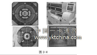
In China, the production and use of non-contact IC card chips are still in their infancy. At present, only a few economically developed cities have piloted in the public transportation, medical insurance and other industries, and achieved good results. With the continuous deepening of the national "golden card project" and the use of non-contact IC cards for resident ID cards, the popularity of contactless IC cards in China will be greatly promoted.
At present, there are two main factors affecting the widespread use of non-contact IC cards: one is the production process of the chip, and the other is the cost. For the cost reduction, there are two main ways, one is to significantly improve the production process; the second is to reduce other aspects of the cost, of which the more important is the chip test related to the quality of the final product. For a chip of a contactless IC card, it cannot be a pure digital circuit test due to the presence of an RF circuit. We can test with a mixed-signal tester, but it is not economical from the hardware loss of the test itself or the test time.
The test solution for the contactless IC card chip described in this article, using the plug-and-play RFID Module, plus some AC/DC test functions of the test system itself as auxiliary verification, can complete the test of the complete RFID chip. Low cost testing is achieved.
Here are some basic performance parameters of the RFID Module:
- Carrier signal frequency: 13.56MHz
- Carrier signal amplitude: O-30Vpp
- Modulation depth: 5%-100%
- Load modulation method: BPSK
April 28, 2024